Mastadon Fuzz kit

Item number: 225

Huge Fuzz for Bass and Guitar.

Category: Fuzz

Enclosure

starting from 24,50 €

Final price incl. VAT, plus shipping (mitttel)

Not available now!


Description

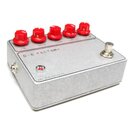
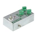
The Mastadon Fuzz is a mammoth-like Fuzz Face variant with 4 separate controls. Due to its great loe-wnd it is excellent for Bass, but of course also for guitar!

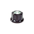
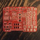
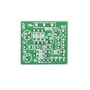
This kit contains the pcb and all necessary parts. You can choose an enclosure, please select 4 knobs for 6,3mm shaft separately.
Here´s a list with the parts in the kit: Bill of materials

This project is by GuitarPCB.com, in cooperation with Musikding. If you have any problem with the content of the kits like missing or wrong parts, please contact Musikding (Klaus). For any technical problem relating to building this project, please contact Barry at GuitarPCB.com forum.

You get full technical support at the GuitarPCB.com forum, membership is free of course.
GuitarPCB Forum.

Here´s the direct link to the building docs, including layout and schematic:
Mastadon Fuzz documentation


Instrument: Guitar Bass
Effect-Type: Fuzz

Video Demo

Ratings (19)

Average product review

3 Stars
2 Stars
1 Star

Share your experience with other customers:

Total entries: 7
5 from 5 great pcb

Great pcb, fast and simple to construct.
The pedal has a lot of bass and gain, a small mod with a PreGain could make it more controllable on guitar, beautiful on bass!

., 22.01.2014
5 from 5 Good !

Easy to build, and works great with bass.

., 06.01.2015
5 from 5 Sounds great

Not difficult to build and sounds great (at least on bass).

., 21.03.2015
4 from 5 Brutal Bass Fuzz

Lots of output.
But hey, I get noise from EQ pot! Sizzling.

., 25.01.2016
4 from 5 Sounds woolly, as advertized

I am reasonably experienced in building electronic circuits.
So let me start with a few little to tiny complaints I have, which I think may reduce the likelihood of a total beginner being 100% successful with this project: (the 1st one is only relevant if you buy the pre-drilled case)
The distance between switch and LED seems off, compared to the holes in the metal case. Which means you have to bend the LED wires quite a bit, and it is possible, I think, that you are unlucky and the outer leads of the LED just touch the metal tube which holds the LED on the front panel, shorting it. Also, I had to remove a plastic plug in that pipe to get the LED through, as the holes in that plug do not match the LEDs leg alignment.
One of the electrolytic capacitors has to be bent so it wont block the way for the switch when mounting the PCB - bad if you soldered it tight and then notice ;) And it still somewhat touches the tip of an inserted plug, being so close to the TRS jack. Not perfect design.

Construction - Saving some time:
You can save some time in construction, IMO:

1) Potentiometers: look at the PDF schematic. 2..3 of the 4 pots, if I recall correctly, short the wiper connector with one of the end connectors. This means you need to solder only 2 wires instead 3 for those pots - one end shorting the two pins on the pot, the other end going into one of the 2 PCB holes for that pot which are shorted on-PCB anyway.

2) Soldering wires to the PCB while it is mounted in the case.
If you solder the wires by sticking the end through the PCB from the top, then turn the PCB, then solder the wire, turn back again, repeat for remaining wires..., I think you take more time as opposed to this:
Mount the completely assembled (all parts soldered) PCB into case which has all pots, jacks, LED etc mounted, by screwing in the switch. Print out the image from the PDF which shows which wire to solder where on the board - *mirrored* horizontally, so you wont get confused by the reversed order of holes when soldering to the, eh, downside-up PCB. (lo-fi but quick way: paste screenshot of the PDF page into e.g. XnView, Image -> Mirror, File -> Print)
Then solder one end of those wires with stripped, lightly tinned ends, to a potentiometer (or power jack or whatever) to give it some stability, then stick the other end about 1/2 way through the corresponding PCB hole, such that a bare part of wire is still above the PCB surface - and you can heat it without hitting any insulation with your soldering tip and dirty it by burnt residues...
Then you can solder the wire into the hole - and because it is tinned and stiff, and all is contained within a sturdy enclosure, neighboring wires are at no risk to get shorted even though 1..2 mm of non-insulated wire will stick out of the board in parallel. Just make sure that there is no stuck-through wire end touching a metal part of e.g. a TRS jack where it gets close to the PCB. If there is such a spot on the PCB, you could cut 3/4 of the tinned wire end and solder it to the mounting hole on the board without, or barely sticking it in.

As for the sound: Like in the miscellaneous YT vids reviewing it. I dont use it for bass, but a guitar with low tuning, quite nice :-)

., 17.11.2016
5 from 5 great sound

Nice kit and easy to build but i think the pinch pot has no use, always at full clockwise to obtain a very nice huge and powerful fuzz sound.

., 05.04.2018
5 from 5 Amazing!

Fun to build and sounds really good!
Great on bass too!

., 23.11.2023
Total entries: 7

Notify me when this product is available

Contact


Other customers have also bought the following items
3PDT footswitch

3PDT footswitch

3,90 € *
Box Type BB

Box Type BB

7,90 € *
The Factory- germanium fuzz kit

The Factory- germanium fuzz kit

starting from 29,00 € *
The Screamer - Overdrive kit

The Screamer - Overdrive kit

starting from 23,50 € *